|
DB Models. Mapping ER-to-Relational Shema |
| Theoretical Knowledge |
|
|
|
| Practical Knowledge |
|
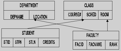
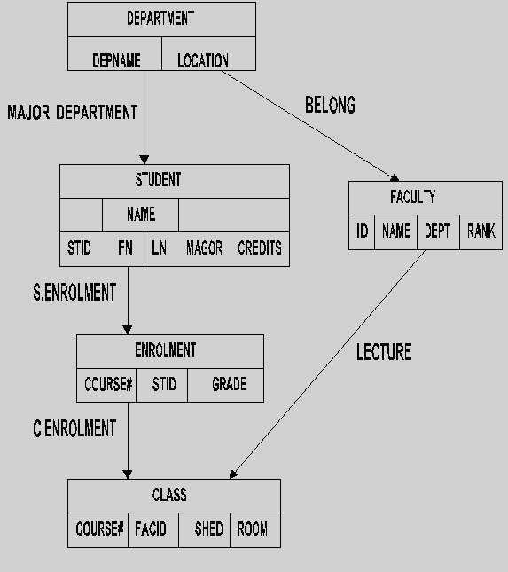
Department
| deptname | location |
Student
| stuid | stfn | stln | credits |
Class
| course# | shed | room |
Step 2: For each weak entity type w
in the ER schema with owner entity type e, we create
a relation r and include all simple attributes (or simple components
of composite attributes) of w as attributes of r. In addition,
we include as foreign key attributes of r the primary key attribute(s)
of the relation that corresponds to the owner entity type e; this
takes care of the identifying relationship type of w. The primary
key of r is the combination of the primary key of the owner and
the partial key of the weak entity type w.
Faculty
f.k.
| deptname | facid | facname | rank |
Step 3: For each binary 1:1 relationship type r in the ER schema, we identify the relations s and t that correspond to the entity types participating in r. We choose one of the relations, s say, and include as foreign key in s the primary key of t. It is better to choose an entity type with total participation in r in the role of s. We include all the simple attributes (or simple components of a composite attribute) of the 1:1 relationship type r as attributes of s.
Step 4: For each regular (nonweak) binary 1:n relationship type r, we identify the relation s that represents the participating entity type at the n-side of the relationship type. We include as foreign key in s the primary key of the relation t that represents the other entity type participating in r; this is because each entity instance on the n-side is related to at most one entity instance on the 1-st of the relationship type. We include any simple attributes (or simple components of a composite attribute) of the 1:n relationship type as attributes of s.
Student
| stuid | stfn | stln | credits | major |
Class
| course# | sched | room | facid |
Step 5: For each binary m:n relationship type r, we create a new relation s to represent r. We include as foreign key attributes in s the primary keys of the relations that represent the participating entity types; their combination will form the primary key of s. We also include any simple attributes of the m:n relationship type (or simple components of a composite attribute) as attributes of s.
Enrolment
| f.k. |
|
| course# | stuid | grade |
Step 6: For each multivalued attribute a, we create a new relation r that includes an attribute corresponding to a plus the primary key attribute k of the relation that represents the entity type or relationship type that has a as an attribute. The primary key of r is then combination of a and k. If the multivalued attribute is composite, we include its simple components.
Faculty_location
| facultyid | location |
Step 7: For each n-ary relationship type r, n>2, we create a new relation s to represent r. We include as foreign key attributes in s the primary keys of the relations that represent the participating entity types. We also include any simple attributes of the n-ary relationship type (or simple components of complete attributes) as attributes of s. The primary key of s is usually a combination of all the foreign keys that reference the relations representing the participating entity types. however, if the participation constrain (min, max) of one of the entity types e participating in r has max = 1, then the primary key of s can be the single foreign key attribute that references the relation e' corresponding to e; this is because in this case each entity e in e will participate in at most one relationship instance of r and can hence uniquely identify that relationship instance.
Student_faculty_class
| stuid | facid | course# | grade |
'Codasyl' model conference on data systems languages (1971)
'DBTG' database task group.
Network model allows representing of 1:n relationships existing between records.
Strictly speaking it does not allow m:n relationships.
'Cheat' is to use link record types.
Definition includes:

Hierarchical models
Do not allow direct representation of many-to-many relationships.
Allowable structures are in the form of trees.

The tree consists only of one-to-many downward pointing links.
A parent can have many children, but a child can have only one parent.
If there is more than one path between any two record types, then the structure is a network, not a hierarchy.

'Relation' = 2-dimensional table
Proposed by dr e.f. codd of ibm in 1970
- Mathematically rigorous basis
Some differences
Logical key pointers
Definitions
Schema - set of relations .
Relation - table .
Attribute - field heading .
Tuple - row on a table .
Column - field entries .
N-tuple - tuple with n attribute values (n = degree) .
Cardinality - no. of tuples in relation .
Domain - set of possible values for an attribute .
Key - record item used to access data schema.
Employees
| ecode | name | address | dob | doe |
| 9491 | smith | 6 shaw st | 130260 | 031078 |
| 7416 | day | 2 sale st | 140143 | 031182 |
Contracts
| ccode | site | begin | end | super |
| 279 | hull | 270685 | 030787 | 9491 |
| 665 | york | 140986 | 020288 | 7416 |
Relational Database Definitions
Draw the relational schema for the examples from the previous session.